Splines & shapes
Pass through a list of points with a smooth spline, and draw circles, rectangles, polygons, helices and spirals in any plane.
Pass through a list of points
To follow a contour or a path given by points, use a spline. The trajectory passes exactly through each point, with a smooth curve between them, and without stopping at the points.
new double[] { 1125, 1125, 1687, 2530, 1265, 2530 });var cartesianLimits = new CartesianLimits(500, 2000, 10000, 90, 360, 1800);var planner = new MotionPlanner(jointLimits, cartesianLimits);// Cartesian spline: passes through each point, with its orientation, at 150 mm/svar contour = new[]{new XYZWPRPosition(550, 40, 300, 180, 0, 0),new XYZWPRPosition(600, 0, 320, 180, 10, 0),new XYZWPRPosition(650, -40, 300, 180, 0, 20),new XYZWPRPosition(700, 0, 300, 180, 0, 0)}.Select(FanucMotion.ToCartesianPose).ToArray();Trajectory cartesian = planner.CreateCartesianPath(FanucMotion.ToCartesianPose(new XYZWPRPosition(500, 0, 300, 180, 0, 0))).MoveSpline(contour, 150, FanucMotion.Fine()).Build();// Joint spline: passes through each joint position, at 40% of the velocity limitsvar via = new[]{new JointValues(20, 10, 0, 0, -90, 0),new JointValues(40, 0, 10, 20, -80, 0),new JointValues(30, -10, 0, 20, -90, 45)};Trajectory joint = planner.CreateJointPath(new JointValues(0, 0, 0, 0, -90, 0)).MoveJointSpline(via, 40, FanucMotion.Fine()).Build();}}
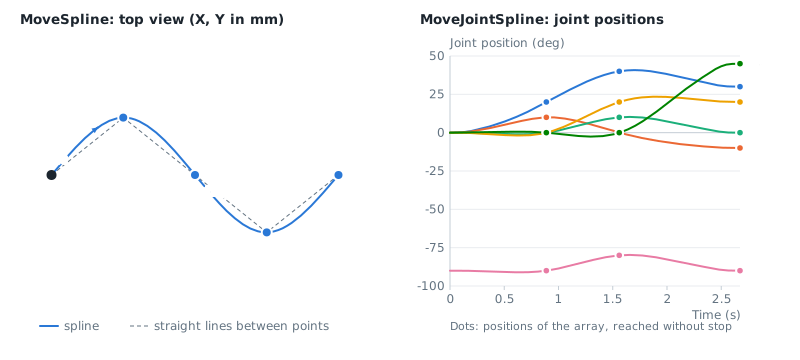
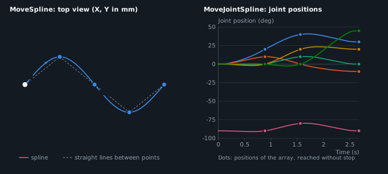
MoveSpline(points, speed, termination)for Cartesian points, at a speed in mm/s. The orientation also passes through the orientation of each point, and the extended axes through their values when the points areExtendedCartesianPosition.MoveJointSpline(points, speedPercent, termination)for joint positions, at a percentage of the velocity limits.- The spline starts at the current position of the builder. A first point equal to this position is ignored.
- The speed is constant along the path, except where the curvature, the change of orientation or the extended axes need a lower speed to stay within the limits.
- A Cartesian spline can be joined to linear and circular motions with a CNT or CR termination, before and after it.
The points must describe a smooth path. Points that are very close to each other or noisy (for example raw measurements) give high curvatures, so the robot slows down. Filter them first. Two consecutive Cartesian points cannot have the same position with different orientations: use MoveLinear() for a change of orientation only.
Draw geometric shapes
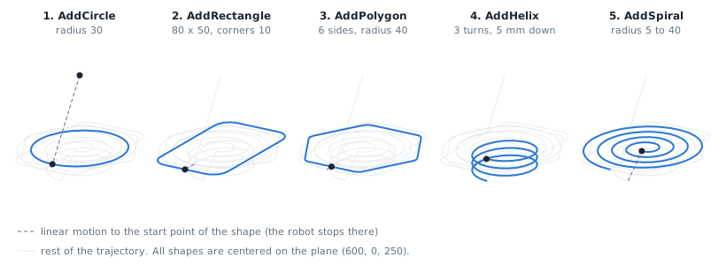
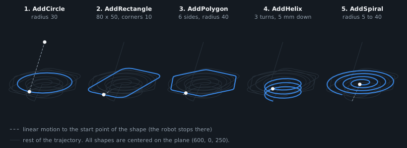
Shapes are drawn in the XY plane of a frame that you give, anywhere in space. The origin of the frame is the center of the shape, and the shapes turn counterclockwise around its Z axis.
new double[] { 1125, 1125, 1687, 2530, 1265, 2530 });var cartesianLimits = new CartesianLimits(500, 2000, 10000, 90, 360, 1800);var planner = new MotionPlanner(jointLimits, cartesianLimits);// Frame of the shapes: origin = center, XY plane = plane of the shapes (here horizontal, in the world frame)var plane = FanucMotion.ToCartesianPose(new XYZWPRPosition(600, 0, 250, 0, 0, 0));var start = FanucMotion.ToCartesianPose(new XYZWPRPosition(600, 0, 300, 180, 0, 0));Trajectory trajectory = planner.CreateCartesianPath(start).AddCircle(plane, 30, 150, FanucMotion.Fine()) // radius 30 mm at 150 mm/s.AddRectangle(plane, 80, 50, 10, 150, FanucMotion.Fine()) // 80 x 50 mm, corners of radius 10 mm.AddPolygon(plane, 6, 40, 5, 150, FanucMotion.Fine()) // hexagon of radius 40 mm, corners of radius 5 mm.AddHelix(plane, 20, -5, 3, 100, FanucMotion.Fine()) // radius 20 mm, 5 mm down per turn, 3 turns.AddSpiral(plane, 5, 40, 4, 100, FanucMotion.Fine()) // from radius 5 to 40 mm in 4 turns.Build();}}
| Method | Shape | Start and end |
|---|---|---|
AddCircle(plane, radius, speed, termination) | Full circle | Point (radius, 0, 0) of the frame |
AddRectangle(plane, width, height, cornerRadius, speed, termination) | Rectangle, width along X, height along Y | Middle of the side at +X |
AddPolygon(plane, sideCount, radius, cornerRadius, speed, termination) | Regular polygon, radius of the circumscribed circle | Middle of the side at +X |
AddHelix(plane, radius, pitch, turns, speed, termination) | Helix around Z, moving by the pitch along Z at each turn | Starts at (radius, 0, 0) |
AddSpiral(plane, startRadius, endRadius, turns, speed, termination) | Spiral in the XY plane, from one radius to the other | Starts at (startRadius, 0, 0) |
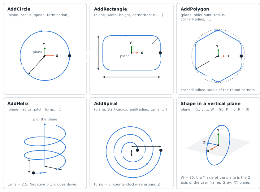
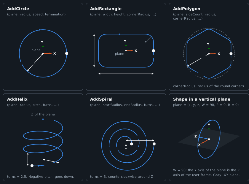
- A linear motion to the start point of the shape is added when the tool is not there. The robot stops at the start point.
- The orientation of the tool and the extended axes do not change during the shape.
- The corners of rectangles and polygons are circle arcs of the corner radius, and the curvature changes progressively at their ends. With a corner radius of 0, the robot stops at each corner.
- The speed is reduced where the curvature needs it: small radii are followed more slowly.
- The frame of the shape is expressed in the user frame of the planner, like the targets.
To make a shape in a vertical plane, turn the frame. For example, with W = 90, the XY plane of the frame is the XZ plane of the world frame.